Z-Stepper

I modified a cheap stair-stepper unit to control the Z-axis channel, or Throttle channel, on the USB Joystick interface according to how fast one is stepping. My personal application for this is to walk within virtual reality environments by physically 'walking' in front of my screen.

Stepper Unit

I purchased a cheap stair-stepper unit online.

Stepper unit as purchased


Origional function

The stepper unit contains an electronic step-counter (and associated very crude calory-burn and distance calculations) which is triggered from a magnetic reed switch. The reed-switch's magnet is in the end of one of the foot-pedal-arms, which moves into and out of range of the switch as that foot pedal moves up and down.

First-version - single-footfall counter.

I removed the step-counter and unplugged it from the wires from the reed switch. I then used prototyping jumper leads to plug the switch into the Digital-2 and Ground pins of an Arduino Leonardo. A 10k ohm pull-up resistor was also connected between Digital-2 and 5V. This is a standard switch-sensor as per the Arduino Button Tutorial. An Arduino Leonardo was used as it was readily available and has the ability to easily emulate USB keyboard/mouse/joystick devices.

The following code performs the reading of the tripping of the switch, measuring the time between the switch-trips, and converting this to a 0-127 value output on the Z-channel of the USB Joystick Device port.

#include "Joystick.h" // Create Joystick Joystick_ Joystick; const int timeout = 2048; // activity timeout to detect when device has stopped moving while switch active. const int reedSwitch = 3; // the pin that the reed switch is attached to const int ledPin = 13; // the pin that the LED is attached to unsigned long thisEvent = 0; // millisecond value for this switch event. unsigned long lastEvent = 0; // millisecond value for last switch even. int output = 0; // the final value of the output to the JS.Z interfare int switchState = LOW; // current state of the button int lastSwitchState = LOW; // previous state of the button int temp = 0; // temporary integer for loops void setup() { Serial.begin(9600); // serial comms for testing and tuning Joystick.setThrottleRange(-127, 127); // set range on Joystick channel to be used. Joystick.begin(); // activate Joystick HID interface pinMode(reedSwitch, INPUT); // the reed switch input pinMode(ledPin, OUTPUT); // test LED lastEvent = millis() - timeout; // set up initial value so timing comparisons work from first run } void loop() { thisEvent = millis(); // update current time //detect high->low transition of switch lastSwitchState = switchState; // save the current state as the last state, for next time through the loop switchState = digitalRead(reedSwitch); // read the pushbutton input pin for current state if (switchState == LOW && lastSwitchState == HIGH) { // switch state has changed from LOW to HIGH (rising edge) output = constrain( map(thisEvent - lastEvent, timeout,0, 0,127),0,127); // calculate the time since last event and turn it into a 0-127 value Serial.print(output); // print output value to console (monitoring for debug) Serial.print("\t"); // print a separator for(temp = 0; temp < output/4; temp++) // loop to print a crude bar-graph of value (monitoring) Serial.print("#"); // print a bar-graph element Serial.println(""); // print a new-line after bar-graph Joystick.setThrottle(output); // send value to USB Joystick HID interface lastEvent = thisEvent; // grab the timing of the switch transition } if ( (thisEvent - lastEvent) > timeout) { // timeout indicates motion has stopped, so send a zero value Serial.println("0\tTIMEOUT"); // print an indicator that intra-event timeout occurred Joystick.setThrottle(0); // send value to USB Joystick HID interface delay(100); // slow timeouts down a bit! } delay(20); // Delay loop a little bit to avoid switch bouncing }

Above we measure the time between 'rising edge' triggers of the switching event (switch going from off to on) rather than just measuring how long the switch is on (or off). This allows for the fact that the user may leave the device with the left pedal down, and hence the switch left on for an extended period of time. If we were measuring just the on-time before sending a fresh value to the Joystick interface, then the end of the measurement would never come and the value before would remain stuck - so even if the user had stopped, the computer would think they were still stepping!

The other alternative is to have a bit of timeout-code running in the 'waiting for off' loop to detect this special case - which is what I first used - but the change to edge-detection of the switch state removed this special case and the extra code to deal with it! Making the code flow simpler by removing special cases is usually a good thing!

The above code should be usable with any device that periodically triggers a switch. Exercise bikes, rowing machines, eliptical trainers, etc. will often have a magnetic reed switch triggered by a magnet in their wheel. Or you can add your own if it doesn't (or you don't want to permonantly modify the built-in monitor equipment). Depending on the switch-triggering speed range, you will have to alter the timeout constant, and may also have to fiddle with values in the map function - though the latter will hopefully be less-often necessary! The Serial.print statements will assist you with monitoring what is going on and get these ranges right. Once you are happy, you can comment out those lines if you like.


Final-version - dual-footfall counter.

While the above worked fine, the main issue with the step counter was that at the lower-walking speed I wanted to measure, there were 2 seconds between left-steps, meaning I had to wait over 2 seconds to find out if the user had stopped walking. Doubling the precision of this involved adding a second reed switch to the other pedal, so I could detect each step, rather than only the left ones!

I also replaced the Arduino Leonardo from the labs where I work, with a Pro-Micro unit I purchased myself. These use exactly the same control chip, but are on a much smaller board, so I can now easily fit it inside the stepper device.

Pro-Micro with wires and resistors attached

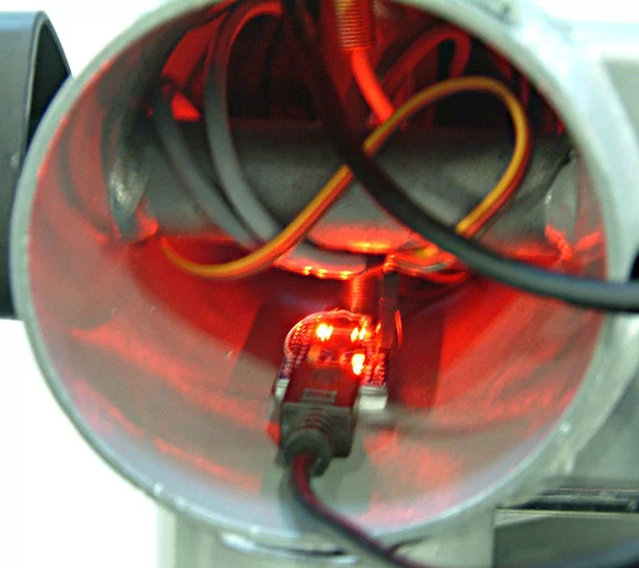
Above you can see 3 wires from the 2 reed-switches - Pins Digital-2 and Digital-3 each come from a different reed switch, and a common GND goes to both of them. Pins Digital-2 and Digital-3 are also connected to 5V via 10k pull-up resistors.

The resistors are not necessary anymore now that the Arduino environment has exposed the chip's own internal pull-up resistors.

See: pinMode(INPUT_PULLUP)


New reed switches were installed in the device (one side shown here). Left - on the pedal-arm - is the magnet-housing and right - in the central column - is the switch housing:

Right-side reed switch installed

Connecting both reed switches in parallel to Digital-2 may have worked with the origional code, except if the stepper was manually set for short-step-height, the on-periods of the switches would overlap and therefore there would be no 'off' to detect. Instead, they were wired to different inputs and the code modified as below:

#include "Joystick.h" // Create Joystick Joystick_ Joystick; const int timeout = 1024; // activity timeout to detect when device has stopped moving const int reedSwitch1 = 2; // the pin that reed switch 1 is attached to const int reedSwitch2 = 3; // the pin that reed switch 2 is attached to const int ledPin = 13; // the pin that the LED is attached to unsigned long thisEvent = 0; // millisecond value for this switch event. unsigned long lastEvent = 0; // millisecond value for last switch even. int lastOutput = 0; // last output value (for averaging/smoothing) int output = 0; // the final value of the output to the JS.Z interfare int switchState1 = LOW; // current state of reed switch 1 int lastSwitchState1 = LOW; // previous state of reed switch 1 int switchState2 = LOW; // current state of reed switch 2 int lastSwitchState2 = LOW; // previous state of reed switch 2 int temp = 0; // temporary integer for loops void setup() { Serial.begin(9600); // serial comms for testing and tuning Joystick.setThrottleRange(-127, 127); // set range on Joystick channel to be used. Joystick.begin(); // activate Joystick HID interface pinMode(reedSwitch1, INPUT); // setup reed switch 1 input pinMode(reedSwitch2, INPUT); // setup reed switch 2 input pinMode(ledPin, OUTPUT); // test LED lastEvent = millis() - timeout; // set up initial value so timing comparisons work from first run } void loop() { thisEvent = millis(); // update current time //detect LOW->HIGH transition of switch 1 lastSwitchState1 = switchState1; // save the current state as the last state, for next time through the loop switchState1 = digitalRead(reedSwitch1); // read the pushbutton input pin for current state //detect LOW->HIGH transition of switch 2 lastSwitchState2 = switchState2; switchState2 = digitalRead(reedSwitch2); if ((switchState1 == HIGH && lastSwitchState1 == LOW)||(switchState2 == HIGH && lastSwitchState2 == LOW)) { // either switch state has changed from LOW to HIGH (rising edge) output = constrain( map(thisEvent - lastEvent, timeout,0, -63,191),0,127); // calculate the time since last event and turn it into a 0-127 value output = (output + lastOutput) / 2; // average the output value with the last one to smooth things out a bit lastOutput = output; // set the new lastOutput value for use next time through Serial.print(output); // print output value to console (monitoring for debug) Serial.print("\t"); // print a separator for(temp = 0; temp < output/4; temp++) // loop to print a crude bar-graph of value (monitoring) Serial.print("#"); // print a bar-graph element Serial.println(""); // print a new-line after bar-graph Joystick.setThrottle(output); // send value to USB Joystick HID interface lastEvent = thisEvent; // grab the timing of the switch transition } if ( (thisEvent - lastEvent) > timeout) { // timeout indicates motion has stopped, so send a zero value Serial.println("0\tTIMEOUT"); // print an indicator that intra-event timeout occurred Joystick.setThrottle(0); // send value to USB Joystick HID interface lastOutput = 0; // reset lastOutput also to zero delay(100); // slow timeouts down a bit! } delay(20); // Delay loop a little bit to avoid switch bouncing }

Above is basically the same functionality except both switches are read independently and either can trigger the output.

I also added a 2-value averaging mechanism for the timing measurements as I was getting different trigger timings off each switch and adjusting the physical positions of the magnets to equalise this was proving too fiddly.

So now the no-activity timeout is down to 1 second.

I also moved the output to the USB Joystick 'Throttle' channel, as I intend to keep the Z-channel for fine-grained motion control via a hand controller unit (this will require some modification to the VR environment's controll interface, but I am presently using the Overte open-source VR environment, which allows such user customisation).


Here is the ProMicro prior to installation in the unit. I also moved the bottom (blank) plastic cap to the top where the origional step-counter display was:

Pro-Micro hanging out of the stepper unit

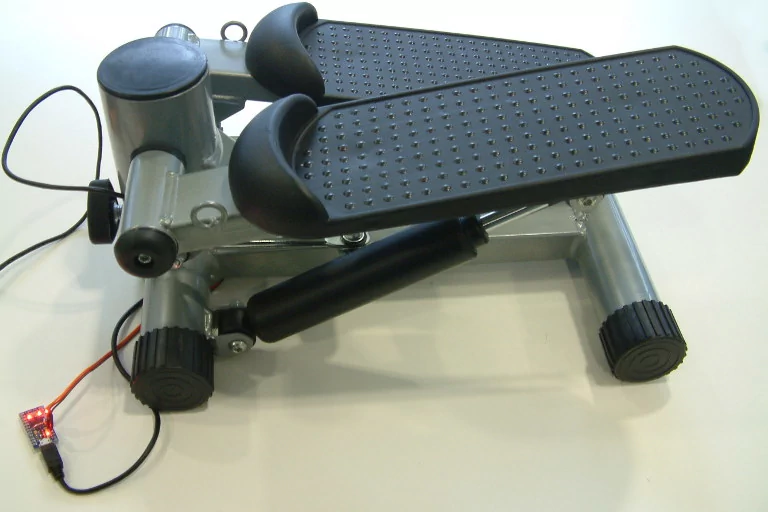
And here it is stuck inside the stepper with two layers of double-sided sponge-foam tape:

Pro-Micro installed inside the stepper unit


One more thing - USB-B socket.

I have now added a USB-B socket to Micro-USB plug so that I can use a standard USB-A-B cable with the device (Micro-B is great for small devices such as phones, but for bulky devices like this, a full-sized B plug is going to be more rugged and user friendly).

USB-B socket to USB-micro plug